Views: 0 Author: Site Editor Publish Time: 2026-08-16 Origin: Site
Selecting the correct electrical switch is rarely a minor design detail. A misapplied switch can easily lead to premature mechanical failure, safety hazards, and costly product recalls. With thousands of variations available, design engineers and procurement teams face a complex challenge daily. They must constantly balance rigorous electrical specifications, tight footprint constraints, and strict regulatory compliance requirements.
You cannot simply guess which component works best. Making the right choice requires a deep understanding of circuit logic, actuation types, and environmental factors. This guide breaks down the core categories of electrical switches. We will explore their precise applications and provide a rigorous evaluation framework. We aim to help ensure your hardware meets lifecycle, safety, and operational standards. By the end of this read, you will know exactly how to specify and evaluate components for your unique manufacturing needs.
Application matching is paramount: Choosing between a micro switch and a detection switch depends entirely on actuation force requirements and space constraints.
Lifespan metrics differ: Mechanical lifespan (physical toggles) often vastly exceeds electrical lifespan (under load); both must be evaluated against the product's intended use case.
Compliance dictates sourcing: Selecting switches without verified UL, ENEC, or CQC certifications introduces severe regulatory and liability risks into the manufacturing phase.
Environmental realities matter: IP-rated sealing is non-negotiable for switches exposed to moisture, dust, or micro-vibrations.
Before diving into specific hardware components, we must establish a clear engineering baseline. Standard switch taxonomy relies heavily on the concepts of poles and throws. A pole refers to a single independent circuit controlled by the switch. A throw indicates how many different positions the switch can connect to. Engineers use these abbreviations universally to describe internal architecture.
These internal configurations directly dictate your circuit's complexity. For instance, an SPST (Single Pole, Single Throw) switch simply turns one circuit on or off. It acts as a basic interrupter. Conversely, a DPDT (Double Pole, Double Throw) switch handles two separate circuits. It can switch each circuit between two different states simultaneously. This capability proves vital for complex fail-safe implementations. The configuration often determines whether you must add a secondary control relay to your board.
Actuation type represents another critical fundamental. We differentiate clearly between momentary and maintained operations. Momentary switches use a built-in spring-return mechanism. They only remain active while the user applies continuous physical force. Maintained switches, often called latching switches, stay locked in their new position until toggled again.
You will find momentary actions common in industrial safety pedals or keyboard keys. Maintained actions typically control main power lines in commercial environments. Selecting the wrong actuation type frustrates users and creates immediate safety risks.
Common Switch Configurations and Circuit Logic
Configuration | Abbreviation | Function Description | Common Use Case |
|---|---|---|---|
Single Pole, Single Throw | SPST | Controls one circuit, offering simple ON/OFF logic. | Basic power buttons, lighting controls. |
Single Pole, Double Throw | SPDT | Controls one circuit, routing it between two distinct paths. | Three-way lighting setups, source selectors. |
Double Pole, Single Throw | DPST | Controls two separate circuits, turning both ON/OFF simultaneously. | Main power disconnects isolating both live and neutral wires. |
Double Pole, Double Throw | DPDT | Controls two circuits, routing each between two separate paths. | Motor reversing controls, advanced routing arrays. |
Different hardware projects demand completely different actuation methods. Let's explore the primary switch categories used widely across global manufacturing.
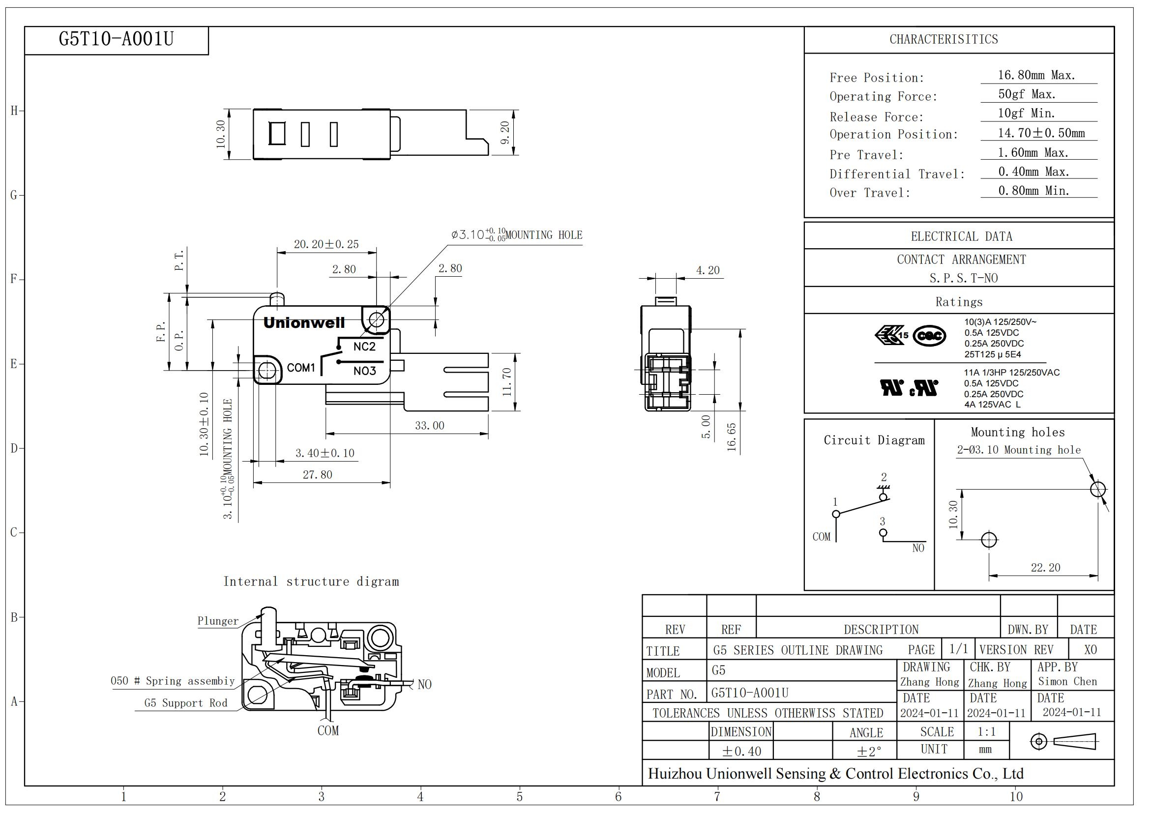
A Micro Switch utilizes a highly engineered tipping-point mechanism. This internal spring design provides rapid, reliable switching using minimal physical force. It snaps the contacts open or closed instantly, regardless of how slowly you press the external actuator. This snap-action prevents dangerous electrical arcing during slow presses.
Engineers frequently choose these components for industrial automation, limit sensing, and critical safety mechanisms. They excel inside CNC machines and automated conveyor systems. When evaluating them, you must look closely at operating force variations. Differential travel specs are also crucial. They tell you exactly how far the actuator must travel back before resetting the internal spring. Overlooking this detail can cause sensing errors in precision equipment.
A Door Switch functions as a rugged, panel-mounted safety component. Manufacturers primarily use them to interrupt live circuits when a physical barrier opens. You see them operating daily in consumer appliances like refrigerators, microwaves, and washing machines. They also protect high-voltage server racks and industrial HVAC enclosures.
Their primary role involves safety and system integrity. Therefore, you must rigorously assess their interlock reliability. Ensuring they meet strict safety compliance standards prevents accidental shocks. A failed door interlock can expose maintenance workers to live currents. You should always prioritize models offering robust, reinforced housings to withstand aggressive, repeated door slams over years of service.
A Rocker Switch serves as a highly visible, user-facing control. These switches rock back and forth on a central pivot. They offer clear visual status indicating ON or OFF states. They dominate control applications like computer power supplies, medical device interfaces, and automotive dashboards.
When integrating them into consumer products, you should heavily consider ergonomic tactile feedback. Users expect a satisfying, firm click when toggling power. Additionally, you must assess the necessity of integrated LED illumination. Lighted variants help users instantly identify system status in dark or busy environments. However, illuminated models require an extra ground pin and slightly more complex wiring.
A Detection Switch provides ultra-compact sensing capabilities. These components detect mechanical movement while requiring far less operating force than standard snap-action alternatives. They do not use a heavy internal spring mechanism. This makes them incredibly lightweight and small.
They excel in extremely tight spaces. Ideal applications include modern consumer electronics, IoT devices, and smart meter tamper detection modules. They are absolutely critical for designs where PCB real estate is heavily constrained. Despite their miniature size, they offer exceptional accuracy for logic-level signaling. Hardware engineers rely on them to tell microcontrollers when a camera lens opens or a battery door closes.
A Rotary Switch operates entirely by rotational movement. This unique design allows users to select multiple circuit states from a single locus. You will find them heavily utilized in test and measurement equipment, industrial control panels, and multi-speed ventilation fans.
Their multi-position capability effectively replaces several separate toggle switches. This cleans up panel layouts significantly. When selecting one, carefully evaluate the internal detent mechanism. A strong detent ensures long-term reliability and precise alignment. It also provides vital resistance to accidental shifting caused by heavy machine vibrations. Weak detents often lead to users stopping the dial between active circuits, causing system faults.
Choosing the right physical form factor is only the first step. You must systematically evaluate electrical specifications to ensure long-term reliability.
You must precisely match the switch’s rating to the electrical load. Failing to do so causes severe hardware failures. It leads directly to electrical arcing, contact welding, or dangerous overheating. Always address the vast physical difference between AC and DC load ratings.
Alternating current (AC) crosses zero volts multiple times per second. This zero-crossing naturally helps extinguish electrical arcs when contacts separate. Direct current (DC) provides a constant, unyielding voltage. Breaking a live DC circuit often creates sustained, damaging arcs. These arcs can easily melt the internal plastic housing. A switch rated safely for 250VAC at 10A might only handle 30VDC at that exact same current. Never assume AC and DC ratings are interchangeable.
Evaluating a switch purely on "1 million mechanical cycles" is a dangerous engineering trap. Mechanical lifespan only measures how many times the physical spring and actuator can move without an active electrical load. The electrical lifespan measures operations while carrying the maximum rated current.
Electrical life might only reach 50,000 cycles for the exact same component. The intense heat of continuous arcing degrades metal contacts much faster than pure mechanical wear degrades the spring. You must design your maintenance schedules around the electrical lifespan if your circuit carries significant power.
You must carefully assess the need for proper ingress protection. Standard indoor, climate-controlled environments might only require IP40 protection. This level merely protects against large dust particles and accidental finger touches. Harsh environments demand much stricter shielding.
Outdoor panels or marine equipment require IP67 ratings for reliable waterproof and dustproof operation. Operating temperature ranges also matter heavily. Extreme cold makes internal plastics brittle and prone to shattering. Extreme high heat severely degrades contact mechanisms and melts seals. Ensure your component carries an official rating for your actual operating environment.
Internal contact material completely dictates signal performance. Standard silver contacts work perfectly for heavy power circuits. Silver conducts electricity exceptionally well. It handles higher currents and minor arcing effortlessly. However, silver tarnishes and oxidizes over time, creating a resistive microscopic film.
For low-current, logic-level data signals (dry circuits), you must use gold-plated contacts. Gold prevents oxidation entirely. It ensures a clean, reliable signal even at micro-ampere levels. Using silver contacts for a 5-volt microcontroller input often results in missed signals due to invisible surface tarnish.
Beyond technical specifications, successful hardware production requires navigating supply chains and complex regulations. Ignoring these factors can halt your production entirely.
You cannot overlook the absolute necessity of sourcing certified components. Ensure your selected switches carry UL marks for North America and ENEC marks for the European market. Adhering to standards like UL 61058 proves your component passed rigorous safety testing. RoHS and REACH compliance remain strictly mandatory globally.
Selecting non-certified parts introduces severe regulatory risks. It can immediately block your market entry. It often triggers costly board redesigns extremely late in the manufacturing phase. Always request verified certification documents from your supplier before ordering bulk quantities.
Every mechanical switch experiences a phenomenon called contact bounce. When the metal contacts hit each other, they literally bounce apart on a microscopic level before settling. This creates multiple rapid ON-OFF signals in a fraction of a millisecond.
Hardware and software teams must implement technical considerations to debounce these signals. This becomes heavily critical in micro and detection switch integrations feeding data directly into microcontrollers. Without proper debouncing capacitors or software delays, a single button press registers as five or six separate inputs. Additionally, equipment exposed to constant micro-vibrations requires stiffer internal springs to prevent false triggers.
Designing a printed circuit board around a highly proprietary, single-source footprint poses immense operational risk. If that specific manufacturer suffers unforeseen delays, your entire production line stops completely. You need strong proactive strategies for ensuring dual-sourcing capability.
Always look for form, fit, and function equivalents early in the design phase. Standardized footprints allow procurement teams to pivot rapidly to alternative suppliers. They can switch vendors without triggering expensive, time-consuming board redesigns. Build a comprehensive Bill of Materials (BOM) listing at least two approved manufacturers for every critical switch.
To avoid analysis paralysis, engineers should follow a structured, step-by-step approach. Use these four steps to narrow down thousands of options into a highly viable shortlist.
Step 1: Define the Load & Logic: Determine exactly what the switch handles first. Is it a heavy 120V power circuit or a 3.3V logic data signal? This baseline instantly decides whether you need robust silver contacts or highly sensitive gold-plated contacts.
Step 2: Determine Constraints: Outline your strict physical limitations. Consider the available PCB space, the required user actuation force, and the desired mounting style. SMD (Surface Mount Device), through-hole, and heavy panel mount options all require entirely different manufacturing processes and assembly lines.
Step 3: Factor the Environment: Assess potential end-user abuse and environmental extremes. Determine your exact IP requirements and thermal limits. Will this product sit in a climate-controlled office, or will it face heavy wash-downs in an agricultural setting?
Step 4: Request Samples & Spec Sheets: Emphasize the vital importance of real-world prototyping. Never rely solely on baseline marketing specs. Review exact manufacturer derating curves carefully before finalizing the BOM. Testing physical samples validates tactile feedback, acoustic click, and mechanical fit.
Specifying electrical switches requires a delicate, highly informed balance. You must closely align mechanical design, electrical load limits, and user experience. Overlooking a single variable, like specific DC load ratings or environmental ingress needs, can compromise the entire product line. True reliability comes from understanding exactly how a physical switch behaves under real-world stresses over time. Proper application matching prevents costly failures and ensures user safety.
We strongly encourage design engineers and procurement buyers to move far beyond baseline specifications. Start requesting testing samples very early in your design phase. Consult directly with component manufacturers or specialized distributors regarding your specific application. Their deep expertise will help you quickly validate your selections, ensure regulatory compliance, and secure a resilient, multi-source supply chain for years to come.
A: While both components sense physical movement, detection switches are generally much smaller. They handle significantly lower currents and operate primarily on logic-level signals. Unlike micro switches, detection switches completely lack a heavy internal snap-action mechanism. This design makes them highly ideal for tight spaces where minimal actuation force is required, such as consumer electronics and small IoT devices.
A: You should never assume an AC-rated switch can safely handle the exact same DC load. Doing so presents severe risks of internal DC arcing. AC voltage drops to zero during its cycle, naturally extinguishing arcs. DC voltage remains constant, allowing dangerous arcs to sustain and melt metal contacts. Always verify the specific, often much lower, DC rating before installation.
A: Contact bounce refers to a natural mechanical spring-back effect. When a switch closes, the metal contacts strike each other and literally bounce a few times before settling completely. This rapid connect-disconnect cycle sends multiple spurious signals to sensitive digital circuits. It requires software delay algorithms or hardware capacitors to debounce the signal for clean, single inputs.
A: A quick rule of thumb involves thoroughly assessing the intended operating environment. For standard indoor, dry environments, an IP40 rating provides completely adequate protection against large dust particles and accidental touches. If your product operates outdoors or faces wet, wash-down environments, you must specify IP65 or IP67 ratings to ensure complete dust and water resistance.