

Views: 0 Author: Site Editor Publish Time: 2026-08-27 Origin: Site


Selecting the wrong switch configuration can lead to circuit logic failures, inadequate electrical isolation, or unnecessary space overruns in panel design. Engineers constantly face strict demands when designing reliable, efficient control interfaces. While physical actuation dictates ergonomics, the internal contact configuration dictates all electrical functionality. Defined by poles and throws, this internal architecture handles the actual current routing. Understanding these variations helps you prevent catastrophic shorts and system malfunctions in critical applications. This guide breaks down the core differences between the four primary configurations used in modern electronics. We provide a practical evaluation framework so you can specify the exact component needed. You will learn how to balance operational, safety, and spatial requirements without over-engineering the final solution. Choosing wisely saves time, reduces wiring complexity, and ensures long-term product reliability.
Poles determine how many independent circuits a switch controls simultaneously; Throws determine how many output paths each pole can route current to.
An SPST Switch acts as a basic on/off control for a single circuit, while an SPDT Switch toggles one input between two distinct outputs.
A DPST Switch provides synchronized on/off control for two isolated circuits (ideal for safely breaking both hot and neutral lines).
A DPDT Switch offers maximum routing flexibility, commonly used for complex logic like motor polarity reversal, but requires a larger footprint and higher budget.
Over-specifying (e.g., using a DPDT where an SPST suffices) needlessly introduces extra failure points and complicates wiring harnesses.
To specify the correct switch, you must first master the fundamental language of electrical contacts. Engineers classify switches based on two primary internal mechanics: poles and throws. These metrics dictate how a switch manipulates electrical current across different circuits.
Definition of a "Pole": A pole represents the number of distinct, electrically isolated circuits the switch controls simultaneously. You can think of a pole as a single input line. A single-pole switch manages only one circuit. A double-pole switch manages two separate circuits at the exact same time. These two circuits remain electrically isolated from one another inside the housing.
Definition of a "Throw": A throw refers to the number of closed contact positions each pole can make. It defines how many electrical paths the input can route current toward. A single-throw switch completes one specific path. A double-throw switch provides a choice between two separate paths, routing the incoming power to either output A or output B.
The Matrix of Switch Types: Combining poles and throws creates the foundation for classifying all standard electromechanical switches in industrial procurement. By mapping one variable against the other, you generate a reliable matrix of Switch Types. This standardized matrix allows designers to quickly filter components based on required logic. Whether you need to isolate high-voltage lines or route low-level sensor signals, identifying the correct pole-to-throw ratio narrows down your component search instantly.
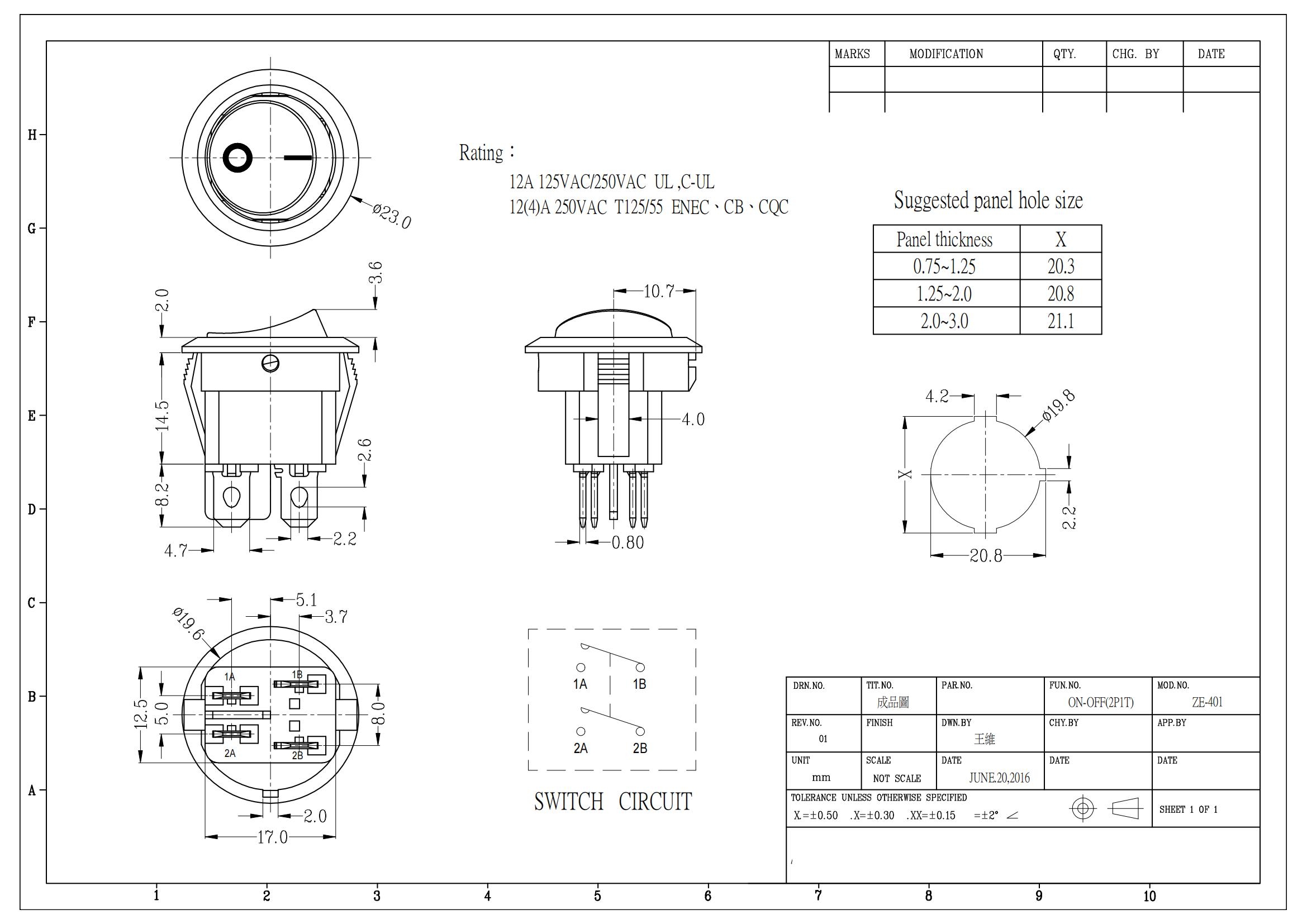
Summary Chart: Core Switch Configurations
Configuration | Terminals | Function | Common Application |
|---|---|---|---|
SPST | 2 | Simple On/Off | Basic lighting, single sensor |
SPDT | 3 | Toggle between two outputs | Standby/main power toggling |
DPST | 4 | Dual isolated On/Off | 240V appliances (hot/neutral break) |
DPDT | 6 | Dual independent routing | Motor direction reversal |
Functionality: This represents the simplest "Make or Break" mechanism available. It features exactly two terminals: one for the input and one for the output. When closed, current flows. When open, current stops.
Best Use Cases: Engineers use the SPST Switch for basic power disruption. You will find them in simple lighting circuits, single-sensor activations, and primary power toggles for low-complexity devices.
Limitations: This configuration cannot route power to an alternate load. It offers no redundancy and provides no secondary signal paths. If you need to trigger a backup system when the main system turns off, an SPST configuration falls short.
Functionality: This configuration routes a single common input to one of two possible outputs. It features three terminals in total. It operates in either an On/On or On/Off/On state. The central terminal receives the current, and the actuator directs it to the chosen output leg.
Best Use Cases: The SPDT Switch excels in three-way lighting circuits. It also works perfectly for standby/main power toggling and simple logic selection. If an operator needs to switch a display from red to green, this component handles the routing effortlessly.
Engineering Note: You must specify "Break-Before-Make" (non-shorting) versus "Make-Before-Break" (shorting) when selecting this component. If your load is sensitive, a shorting switch can cause a momentary overlap where both outputs receive power. Always verify the transition behavior.
Functionality: Think of this as two completely isolated SPST switches operated by a single mechanical actuator. It features four terminals. It turns two independent circuits on or off at the exact same moment.
Best Use Cases: You will frequently see the DPST Switch in 240V appliances. It safely and simultaneously breaks both the live and neutral lines. This guarantees enhanced safety and compliance during maintenance. You can also use it to control two separate voltages—like a 5V DC signal and a 120V AC line—using one physical button press.
Common Mistake: Do not tie the inputs together unless specifically required. The primary advantage here is electrical isolation. Bridging the poles negates the safety benefits of the dual-circuit design.
Functionality: This configuration combines two independent SPDT switches tied to one shared actuator. It features six terminals. It routes two separate inputs to two separate sets of outputs simultaneously.
Best Use Cases: The DPDT Switch provides maximum routing flexibility. Engineers rely on it heavily for motor direction reversal using an H-bridge configuration. It also handles complex A/B testing circuits and multi-signal routing across diverse communication panels.
Engineering Note: Because this switch handles high physical complexity, it demands careful PCB layout. You must ensure adequate spacing between the six terminals to prevent accidental bridging during the soldering process.
Specifying the correct switch requires more than just counting terminals. You must evaluate the component against strict operational and environmental parameters. Use this framework to narrow down your choices effectively.
Circuit Logic & Isolation Needs: First, assess the fundamental logic. If your system requires alternate routing between two loads, you require a double throw. If you must manipulate two isolated circuits safely, you require a double pole. Map out your schematic before looking at physical hardware.
Electrical Load Profiles: Voltage and current ratings are not universal. A switch rated for 15A AC may only be rated for 2A DC. DC circuits lack the zero-crossing point found in AC circuits. This creates severe inductive kickback and arcing risks when breaking DC loads. Always verify the specific rating for your load type.
Physical Constraints & Form Factor: Multi-pole and multi-throw configurations naturally require more internal mechanics. Evaluate your panel depth limits and terminal footprint constraints. A six-terminal switch consumes significantly more PCB real estate than a two-terminal alternative. Evaluate pitch requirements before defaulting to complex switches.
Compliance & Environment: Identify necessary certifications early in the design phase. Look for UL, CSA, or CE marks depending on your regional market. Furthermore, assess the deployment environment. If the panel faces moisture or heavy dust, select a switch with a high IP rating (such as IP67) to prevent internal corrosion.
Even with the correct schematic, poor implementation can ruin system reliability. Be aware of these common pitfalls when designing your wiring harnesses and control panels.
The Cost of Over-Specifying: Using a complex switch and leaving terminals empty to simulate a simpler one introduces distinct risks. For example, using a six-terminal switch to perform a two-terminal job increases unit cost and wastes physical space. Furthermore, the unused internal mechanisms still create unnecessary mechanical resistance. This extra friction can degrade the actuator over time.
Terminal Crowding and Arcing: Double-pole configurations require careful wiring to prevent cross-circuit arcing. This becomes a severe risk when mixing high and low voltages in a confined housing. If you route 120V AC adjacent to a 5V DC data line on a crowded switch base, a tiny stray wire strand can destroy your entire microprocessor board. Always use proper heat shrink and verify terminal spacing.
Actuation Lifespan: You must recognize that switches with more moving parts generally have slightly lower mechanical lifecycle ratings. Structurally simpler components boast incredibly high mean-time-between-failure rates. Every extra pole and throw adds springs, contacts, and pivots. If your application requires millions of actuations, specify the simplest logic possible to maximize mechanical longevity.
Moving from prototype to production requires a disciplined selection process. Taking the time to verify specifications prevents costly redesigns late in the manufacturing cycle.
Shortlisting Logic: Always base your initial selection strictly on required logic (Poles/Throws). Once you filter out incompatible logic, narrow the list by electrical ratings. Finally, finalize your choice based on form factor and environmental sealing. Do not reverse this process.
Actionable Advice: Always request detailed datasheets before bulk ordering. Verify the exact terminal layout and electrical isolation specifications. It is highly recommended to order physical samples and test them in your specific PCB or panel design. This ensures the actuation feel matches user expectations and the terminal pitch aligns perfectly with your automated soldering equipment.
Matching the exact switch configuration to the circuit's logic and safety needs is the first step in reliable system design. Every additional pole or throw changes the electrical architecture and footprint of your panel. By understanding the distinct roles of these four core configurations, you eliminate guesswork from your engineering process.
More poles and throws do not inherently mean a "better" switch. True efficiency, reliability, and regulatory compliance come from specifying precisely what the application dictates and nothing more. Over-engineering introduces unnecessary failure points.
Consult your engineering team today to review your current schematics. Request product samples to physically verify form factors. View the technical catalog for specific models to ensure you have the exact component required for your next project.
A: Yes, you can achieve this by only wiring one common terminal and one output terminal. However, this is inefficient for production runs. It leads to higher unit costs, demands larger space requirements, and introduces unnecessary mechanical wear points.
A: Configuration (Poles/Throws) dictates the electrical paths, while operation (Momentary/Latching) dictates mechanical behavior. Any of the four configurations can be manufactured to spring back (momentary) or stay in place (latching) upon actuation.
A: A DPST switch guarantees simultaneous actuation of both circuits. This proves critical for safety. Breaking hot and neutral lines simultaneously prevents dangerous out-of-sync circuit states that independent switches might cause.


